General Engineering
Oily Water Separator: Control Panel, Pump Module and Separator Tank
Exam reference: GS-0153 (the label exam questions use for this figure)
What the figure shows
Three modules are drawn. A control room panel has an alarm light reading OIL CONTENT EXCEEDS ALARM LIMIT and a PPM display. An engine room pump module has a motor, pump, valves and gauge. A cutaway separator tank shows a gauge, relief valve, internal baffles, plates and a drain. Numbered arrows 1 to 25 point to components.
How to read it
- Identify which module each number falls in: control panel, pump module or separator tank.
- Inside the tank cutaway, look at the baffles and plates that keep separated oil apart from incoming water.
- For mode questions, trace the flow path through the numbered valves rather than reading valves one at a time.
What exam questions ask
- The function of item 7. It prevents separated oil from mixing with the incoming bilge water, so the oil is not carried back through the unit.
- Which valves are open in backflush mode. Backflush reverses the normal flow; the key gives valves 4 and 14 as open, with valve 5 not open.
Common mistakes
- Item 7 is not the part that discharges accumulated oil or directs flow onto the coalescer bed; those are different functions.
- Valve 5 is not open in backflush mode, so any set that includes it does not match the key.
Related figures
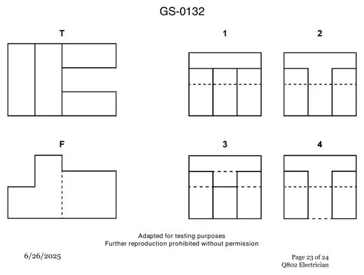 General EngineeringThird Angle Projection: Right Side View
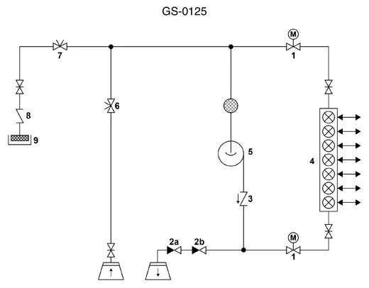 General EngineeringPiping Schematic With Numbered Valve Symbols
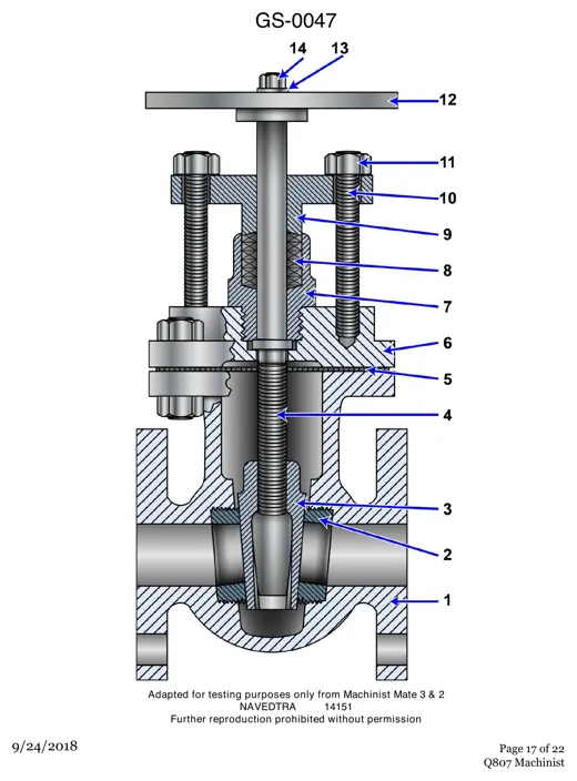 General EngineeringGate Valve Cutaway: 14 Numbered Parts
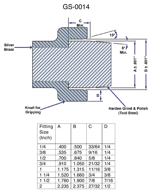 General EngineeringHose Fitting Detail With Dimension Table
 General EngineeringVertical Lube Oil Pump Dimensions and Data
 General EngineeringLimit Sensor Assembly Drawing and Ports