General Engineering
Left Hand Limit Sensor Assembly: Dimensions and Port Threads
Exam reference: GS-0010 (the label exam questions use for this figure)
What the figure shows
A dimensioned drawing of a small manifold block in side view and top and bottom views. Callouts name the sensing gap, switch capsule, manifold assembly, two mounting holes, and the supply and output ports marked 1/8-27 NPT. Dimensions in inches run from .125 up to 2.00.
How to read it
- Find the two ports, supply and output, and their thread callout of 1/8-27 NPT.
- Break a thread callout into parts: nominal size (1/8), threads per inch (27), then the letters.
- Use the side view for the sensing gap and switch capsule.
What exam questions ask
- What the letters NPT indicate in a port callout. They name the thread series, National Pipe Thread taper; the 1/8 is size and the 27 is threads per inch.
Common mistakes
- Reading NPT as a thread profile, class of fit or class of finish. None of those is what the letters name.
Related figures
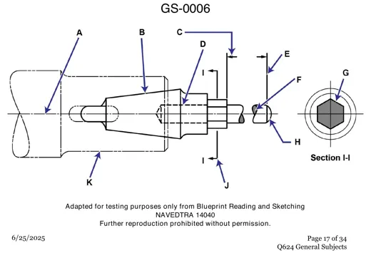 General EngineeringPropeller Shaft Taper Drawing: Line Types
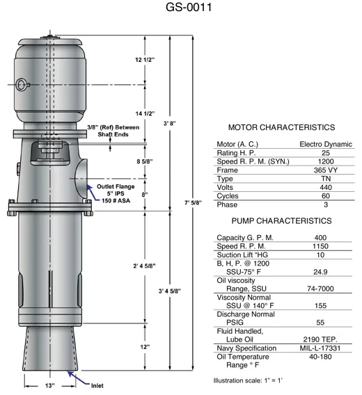 General EngineeringVertical Lube Oil Pump Dimensions and Data
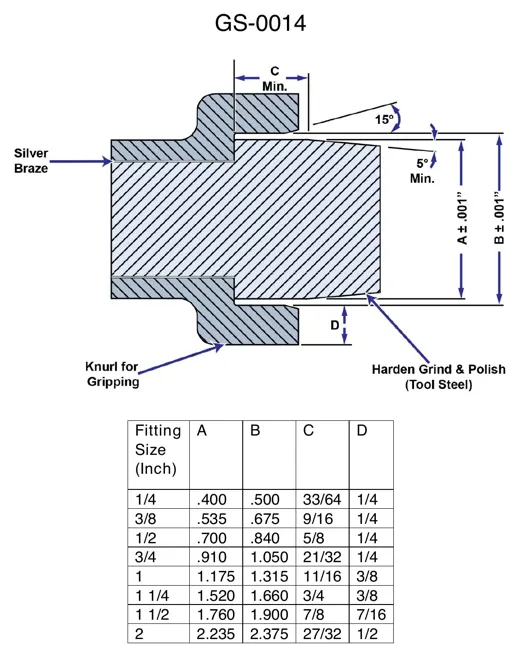 General EngineeringHose Fitting Detail With Dimension Table
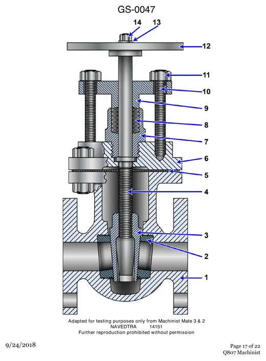 General EngineeringGate Valve Cutaway: 14 Numbered Parts
 General EngineeringPiping Schematic With Numbered Valve Symbols
 General EngineeringThird Angle Projection: Right Side View