General Engineering
Piping System Schematic With Numbered Valve and Fitting Symbols
Exam reference: GS-0125 (the label exam questions use for this figure)
What the figure shows
This line drawing uses standard symbols, numbered 1 to 9. It shows motor-operated valves (1), shut-off valves 2a and 2b, a check valve (3), a bank of seven crossed-circle outlets (4), a circular pump or tank symbol (5), throttle valves (6 and 7), a swing check valve (8) and a hatched tank (9). Trapezoid symbols with up and down arrows mark system connections.
How to read it
- Read each number against its symbol shape: valves, check valves and throttle valves look different.
- Item 4 is the row of seven crossed-circle outlets joined to one line, which is how the schematic shows several branches on a common header.
What exam questions ask
- What item 4 represents. It is a manifold: a header with several connections that joins branch lines to one common line.
Common mistakes
- A suction line or vacuum branch is a single pipe, and a bilge system is a whole system, so none of them fits one multi-connection header.
Related figures
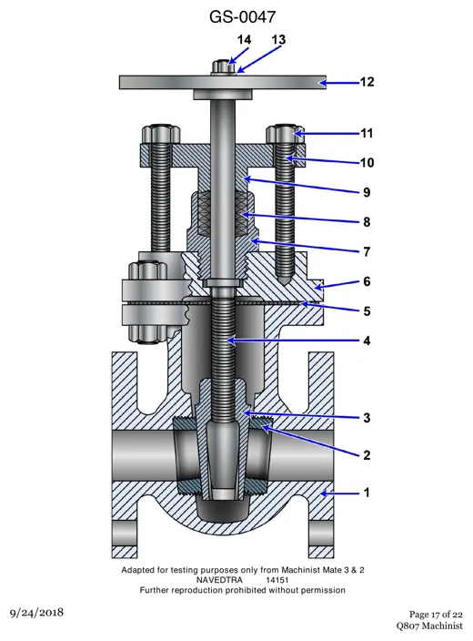 General EngineeringGate Valve Cutaway: 14 Numbered Parts
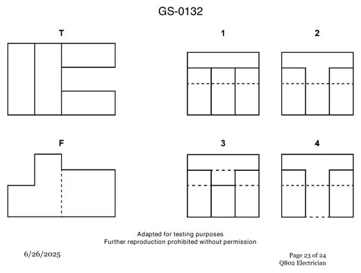 General EngineeringThird Angle Projection: Right Side View
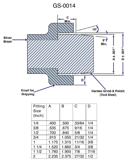 General EngineeringHose Fitting Detail With Dimension Table
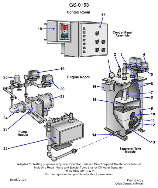 General EngineeringOily Water Separator Parts, Numbered 1 to 25
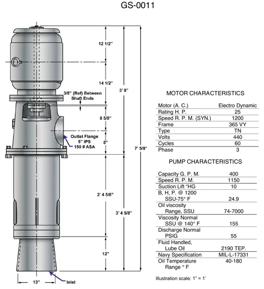 General EngineeringVertical Lube Oil Pump Dimensions and Data
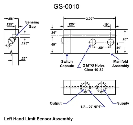 General EngineeringLimit Sensor Assembly Drawing and Ports