Diesel & Motor Plants
Twin Turbocharger Intake and Exhaust Layout on a V Engine
Exam reference: MO-0177 (the label exam questions use for this figure)
What the figure shows
An isometric drawing traces paired exhaust manifolds into two turbochargers, then compressed air through an aftercooler box and back to the air manifolds. A color legend separates exhaust gas, inlet air, compressed air and water. Circled numbers 1 to 9 point to the manifolds, a valve, the compressors, the turbines and the cooler.
How to read it
- Start with the legend so you can tell exhaust gas, inlet air, compressed air and water lines apart.
- Count the turbochargers and follow which exhaust manifold feeds each turbine.
- Follow the compressed air from each compressor through the cooler to the air manifolds.
What exam questions ask
- How many turbochargers the engine uses and how they connect: two units, one for each cylinder bank, working side by side rather than in series, which reduces exhaust back pressure.
Common mistakes
- Treating the two turbochargers as a series, two-stage boost arrangement. Each bank has its own turbocharger, so they work in parallel.
Related figures
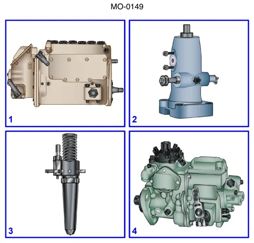 Diesel & Motor PlantsFour Diesel Fuel Injection Units Compared
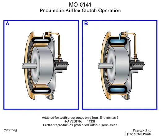 Diesel & Motor PlantsPneumatic Airflex Clutch: Two Operating Views
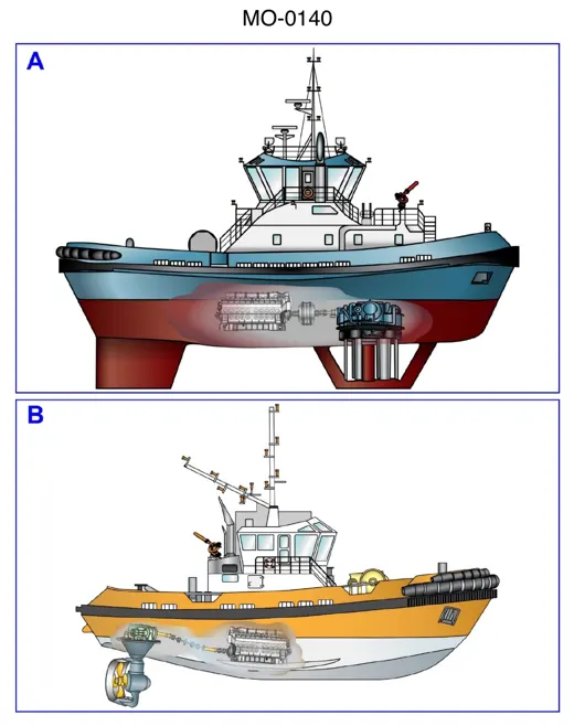 Diesel & Motor PlantsTug Drives: Vertical Blades vs Steerable Pod
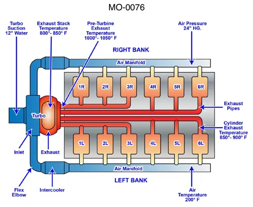 Diesel & Motor PlantsTurbocharged 12-Cylinder Diesel Air Flow
 ElectricalRegulated DC Power Supply and Waveforms
 ElectricalFour 12-Volt Batteries in Series-Parallel