Electrical
Regulated DC Power Supply Schematic with Test Points and Output Waveforms
Exam reference: EL-0085 (the label exam questions use for this figure)
What the figure shows
A schematic divided into stages A to D. It includes transformer T1, test points TP1 to TP5, diodes D1 and D2, inductor L1, capacitor C1, resistor R1, transistor Q1, zener diode CR1 and load RL. Below it, five waveform boxes E to I show half wave pulses, full wave pulses, a flat line, a ripple, and a full AC sine wave, four of them with an average level marked.
How to read it
- Follow the stages A to D from transformer T1 to load RL, noting which components sit in each stage.
- Match each test point TP1 to TP5 with the waveform boxes E to I to see how the signal changes stage by stage.
- In stage D, find CR1 and see how it connects to the base of transistor Q1.
What exam questions ask
- The name of CR1 in stage D. It is a zener diode, which operates in reverse breakdown and holds a nearly constant voltage.
- The job of CR1. It sets a constant reference voltage at the base of the pass transistor Q1 in the series regulator.
Common mistakes
- Smoothing ripple is the filter capacitor's job, not the zener diode's.
- Converting AC to DC happens in the rectifier section; CR1 is a reference, not a rectifier.
Related figures
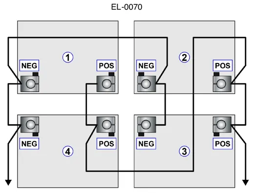 ElectricalFour 6-Volt Batteries in a Parallel Bank
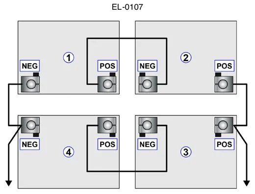 ElectricalFour 12-Volt Batteries in Series-Parallel
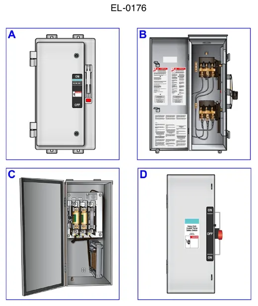 ElectricalSafety Switches: Double Throw Disconnect Views
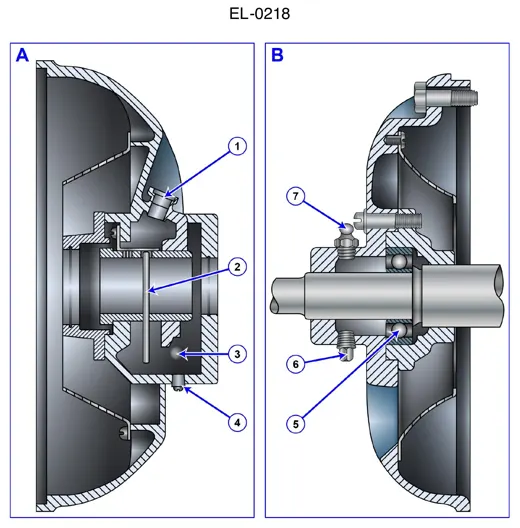 ElectricalMotor Bearing Housings: Grease Fittings, Drain
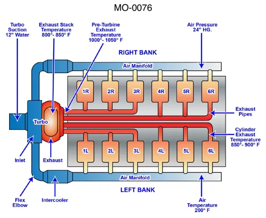 Diesel & Motor PlantsTurbocharged 12-Cylinder Diesel Air Flow
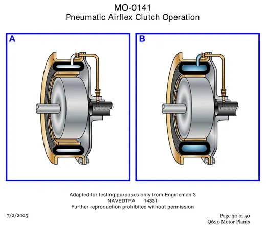 Diesel & Motor PlantsPneumatic Airflex Clutch: Two Operating Views