Diesel & Motor Plants
Four Diesel Fuel Injection Components: Pump and Injector Recognition
Exam reference: MO-0149 (the label exam questions use for this figure)
What the figure shows
Four numbered boxes, each holding one fuel system device. Box 1 is a tan multi-cylinder in-line injection pump with six top fittings, box 2 a blue vertical cylindrical unit with a flange base, box 3 a black tapered unit with a coil spring and side levers, and box 4 a green compact pump assembly with a lever on its front.
How to read it
- Count the fittings on top of each unit: box 1 has six, while box 4 is a single compact pump assembly.
- Sort the four boxes into equipment types such as in-line pump, unit injector, governor or distributor type pump.
What exam questions ask
- Which box shows a rotary plunger distributor pump, where one rotating plunger delivers fuel to each cylinder in turn through a distributor head. Box 4, the compact pump assembly, is that unit.
Related figures
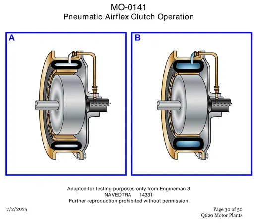 Diesel & Motor PlantsPneumatic Airflex Clutch: Two Operating Views
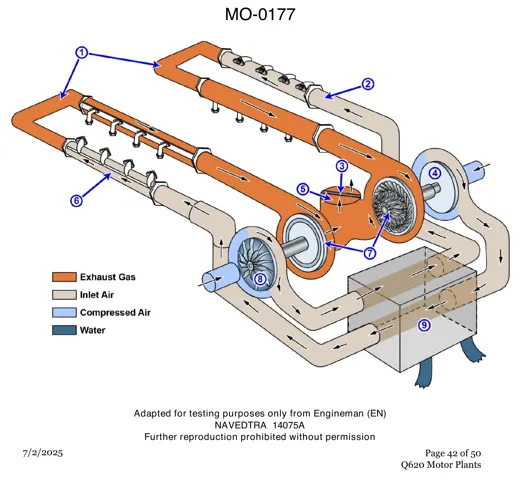 Diesel & Motor PlantsTwin Turbocharger Layout on a V Engine
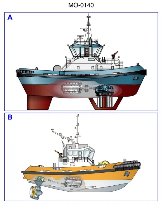 Diesel & Motor PlantsTug Drives: Vertical Blades vs Steerable Pod
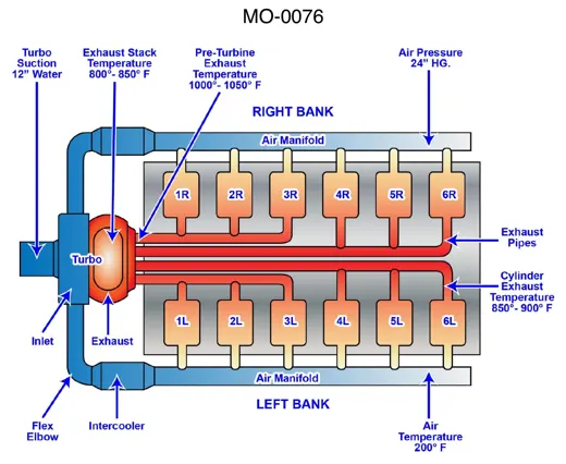 Diesel & Motor PlantsTurbocharged 12-Cylinder Diesel Air Flow
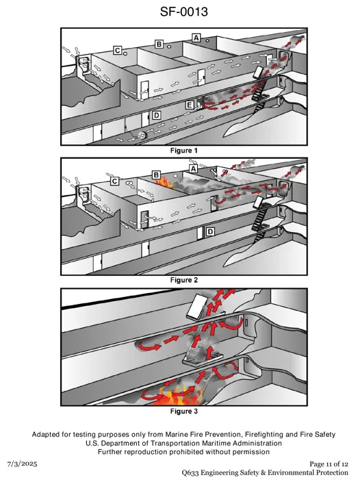 Engineering SafetySmoke and Air Flow in a Shipboard Fire
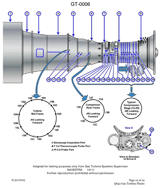 Gas TurbinesGas Turbine Borescope and Probe Port Map