Diesel & Motor Plants
Two Tug Propulsion Arrangements: Vertical Blade Drive and Steerable Pod
Exam reference: MO-0140 (the label exam questions use for this figure)
What the figure shows
Two side views of tugboats with cutaway engine rooms. In A, a diesel engine drives through a coupling to a vertical drive unit with blade type propeller cylinders below the hull. In B, a diesel engine turns a long shaft to a steerable pod style propeller unit at the stern.
How to read it
- Look below the hull: blades hanging down from a rotating unit mark drawing A, while a pod at the stern marks drawing B.
- Note where each drive sits along the hull, since A is under the hull and B is at the stern.
What exam questions ask
- Which propulsion type drawing A shows: a cycloidal propeller drive, with blades on a rotating disc whose pitch changes through a linkage to give thrust in any direction without turning the unit.
Common mistakes
- Do not confuse the cycloidal drive with an azimuthing z-drive, which turns the whole drive unit about a vertical axis to direct thrust.
- A controllable pitch propeller changes pitch on a conventional horizontal shaft, not on a vertical-axis rotor.
Related figures
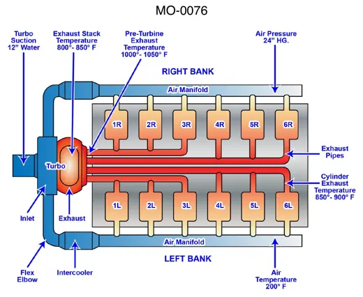 Diesel & Motor PlantsTurbocharged 12-Cylinder Diesel Air Flow
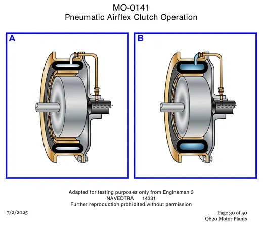 Diesel & Motor PlantsPneumatic Airflex Clutch: Two Operating Views
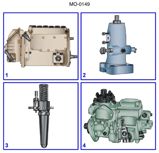 Diesel & Motor PlantsFour Diesel Fuel Injection Units Compared
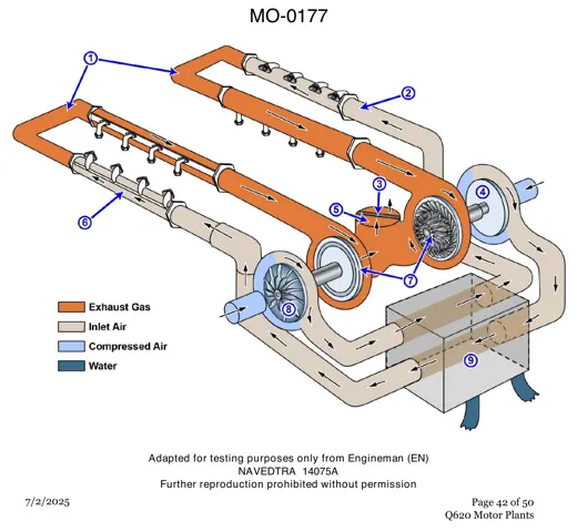 Diesel & Motor PlantsTwin Turbocharger Layout on a V Engine
 Engineering SafetySmoke and Air Flow in a Shipboard Fire
 Gas TurbinesGas Turbine Borescope and Probe Port Map