Diesel & Motor Plants
Turbocharged 12-Cylinder Diesel Intake and Exhaust With Operating Values
Exam reference: MO-0076 (the label exam questions use for this figure)
What the figure shows
A plan view of a twelve cylinder engine, right bank 1R to 6R and left bank 1L to 6L, with air manifolds, an intercooler, a flex elbow and the turbocharger at the left end. Callouts give typical values: turbo suction 12 inches of water, 24 inches HG air pressure, 200 F air temperature, and exhaust temperatures at the cylinders, before the turbine and at the stack.
How to read it
- Start at the turbo suction callout, then follow the air through the intercooler and manifolds to the cylinders.
- Follow the exhaust side back from the cylinders to the turbine and stack, comparing the temperature callouts at each point.
What exam questions ask
- What happens to the vacuum at the blower inlet when load rises from half to full. The engine uses more air, so the pressure drop and the vacuum both increase.
- What turbocharging arrangement is used. It is pulse turbocharging, where exhaust from cylinders with non-overlapping firing is grouped so each blowdown pulse drives the turbine.
Common mistakes
- Expecting the inlet to turn positive under load. The blower inlet stays below atmospheric pressure.
- Confusing pulse with constant pressure turbocharging, which collects all exhaust in one large manifold to smooth the pulses.
Related figures
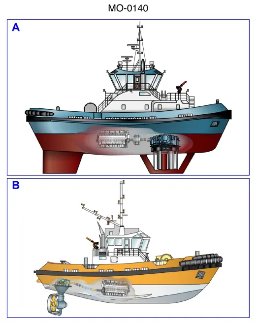 Diesel & Motor PlantsTug Drives: Vertical Blades vs Steerable Pod
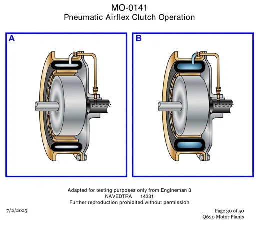 Diesel & Motor PlantsPneumatic Airflex Clutch: Two Operating Views
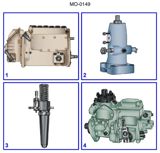 Diesel & Motor PlantsFour Diesel Fuel Injection Units Compared
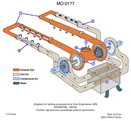 Diesel & Motor PlantsTwin Turbocharger Layout on a V Engine
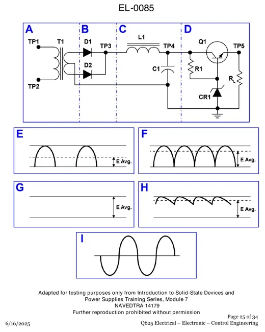 ElectricalRegulated DC Power Supply and Waveforms
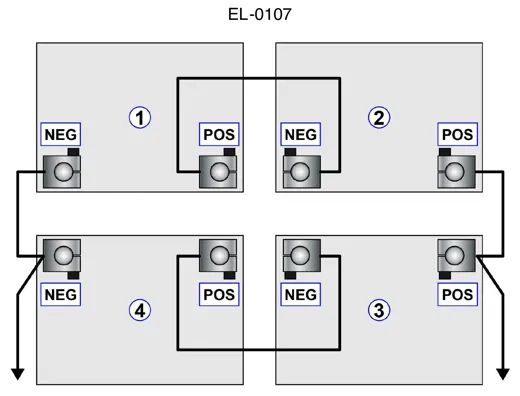 ElectricalFour 12-Volt Batteries in Series-Parallel