Gas Turbines
Gas Turbine Lube Oil, Scavenge and Sump Air System Schematic
Exam reference: GT-0024 (the label exam questions use for this figure)
What the figure shows
A block flow diagram of a gas turbine oil system with sumps A, B, C and D, a lube and scavenge pump, filters, check and bypass valves, an oil cooler, an oil tank and a separate assembly group. A legend gives a line style for each of oil supply, scavenge oil, sump vent air, seal pressure air and seal drain.
How to read it
- Learn the legend line styles first; supply, scavenge, vent air, seal air and seal drain each look different.
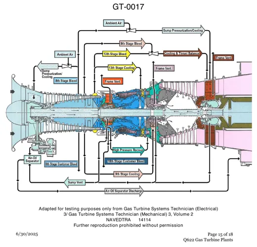
- Follow the sump vent air lines from the four sumps to see where vented air is sent.
What exam questions ask
- What the air/oil separator does. It removes oil from the vapor vented from the sumps, cutting oil loss before the air goes overboard.
Common mistakes
- Thinking it maintains sump oil pressure. The vent exists to prevent pressure or vacuum building in the sump.
- Choosing every listed purpose. Reducing foaming is not its stated job, so only the oil-loss purpose applies.