Gas Turbines
Gas Turbine Control Console: Fuel Oil Panel and Engine Module Panel
Exam reference: GT-0016 (the label exam questions use for this figure)
What the figure shows
A console graphic split into a Fuel Oil panel on the left and a gas turbine module panel on the right. It has red, orange and green alarm and status lights, pump FAST, SLOW and STOP buttons, vertical temperature and pressure scales, water wash, start counter, timer and manual start buttons, speed and power turbine inlet gauges, and emergency controls with an emergency stop.
How to read it
- Use the left panel for fuel oil pumps and the right panel for the engine module itself.
- Find the speed and temperature indications, since the start sequence is judged by gas generator speed and gas temperature.
- Locate the emergency controls and emergency stop at the lower part of the module panel.
What exam questions ask
- The order of events after an auto-start begins. The gas generator reaches ignition speed, light-off is confirmed by gas temperature above 400 degrees F, then the gas generator reaches idle speed.
Common mistakes
- Keying the sequence to power turbine speed. Ignition and idle are both judged on gas generator speed.
- Putting idle speed before light-off. Temperature must confirm ignition before the engine is brought to idle.
Related figures
 Gas TurbinesGas Turbine Borescope and Probe Port Map
 Gas TurbinesLM2500 Cooling and Sealing Air Paths
 Gas TurbinesSelf-Synchronizing Clutch Cutaway
 Gas TurbinesLM2500 Internal Air System Cross Section
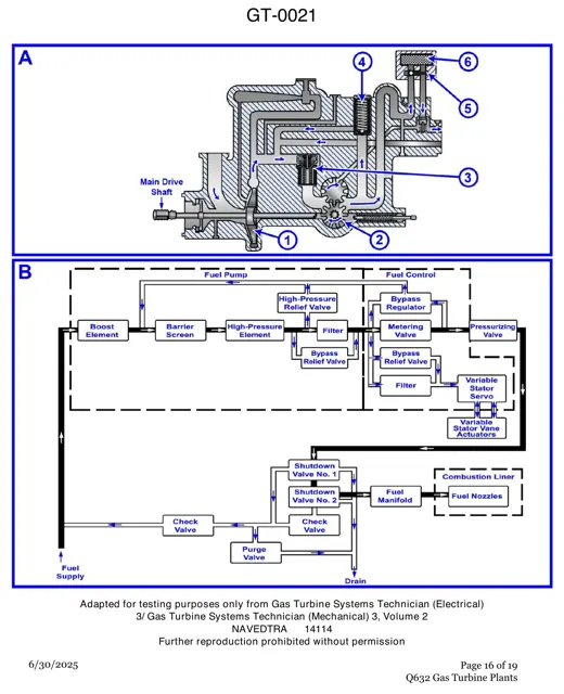 Gas TurbinesGas Turbine Fuel Pump and Control Flow
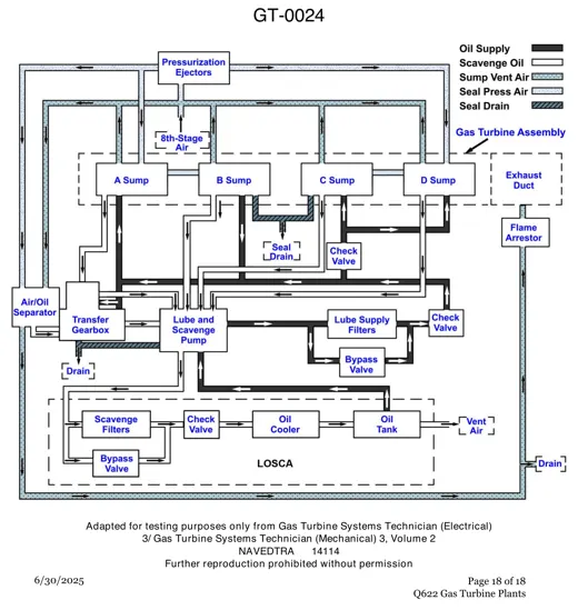 Gas TurbinesGas Turbine Lube, Scavenge and Vent Lines