Gas Turbines
Gas Turbine Fuel Pump Cutaway and Fuel System Block Diagram
Exam reference: GT-0021 (the label exam questions use for this figure)
What the figure shows
Panel A is a cutaway of a fuel pump and control housing with numbered parts 1 to 6, a main drive shaft, gears, springs and flow arrows. Panel B is a block diagram running from the fuel supply through the boost element, barrier screen, high-pressure element, filters, relief valves, bypass regulator, metering valve, pressurizing valve, variable stator servo, shutdown valves and fuel manifold to the nozzles, with drain and check valves.
How to read it
- Use panel B to follow the flow order, starting at the fuel supply and ending at the nozzles in the combustion liner.
- Look for the return paths from the relief valves and bypass regulator back toward the pump.
- Use panel A only for the physical parts, numbered 1 to 6, inside the pump housing.
What exam questions ask
- Where remaining fuel goes when the engine fuel valves are de-energized. It recirculates back to the fuel pump inlet.
Common mistakes
- Sending it to the day tank or the purge manifold. Neither is the recirculation return here, and the high-pressure relief valve only guards against overpressure.
Related figures
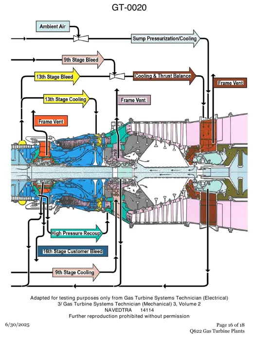 Gas TurbinesLM2500 Internal Air System Cross Section
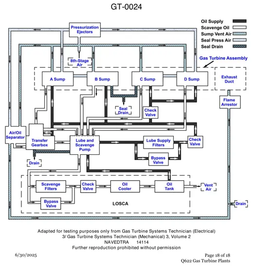 Gas TurbinesGas Turbine Lube, Scavenge and Vent Lines
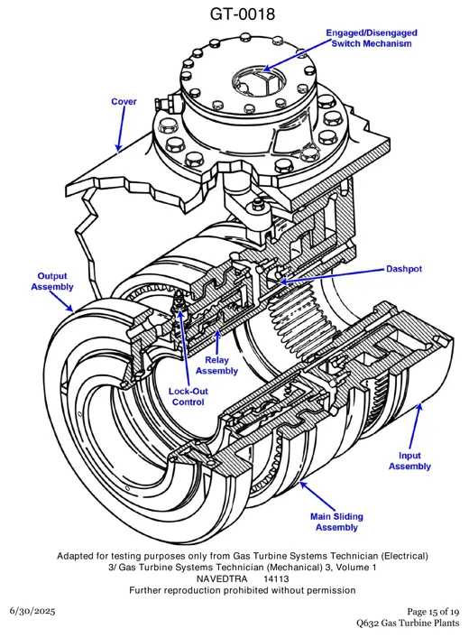 Gas TurbinesSelf-Synchronizing Clutch Cutaway
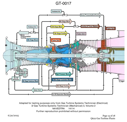 Gas TurbinesLM2500 Cooling and Sealing Air Paths
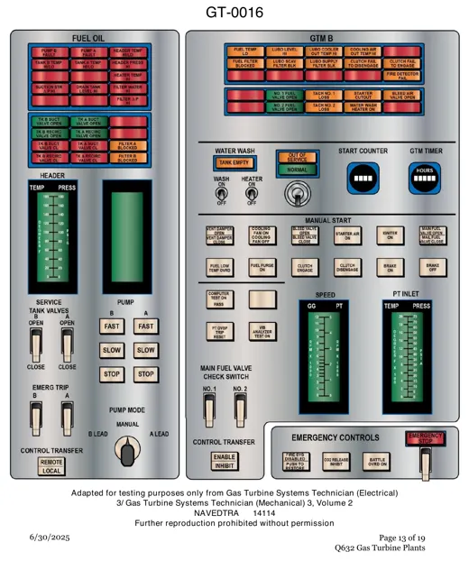 Gas TurbinesGas Turbine Fuel Oil and Module Console
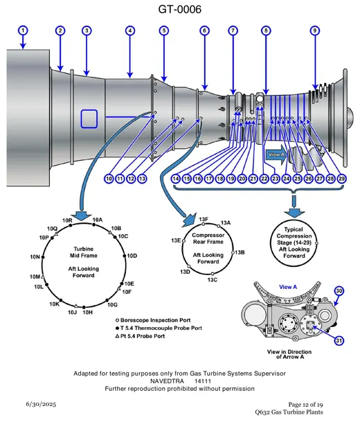 Gas TurbinesGas Turbine Borescope and Probe Port Map